ON30 Layout
Over the last few years club members have constructed a large number of ON30 scale modules which wi exhibit at various train shows in the local area. In general, no two layouts are the same, but we typically have a layout that is around 60 by 20 feet in size.
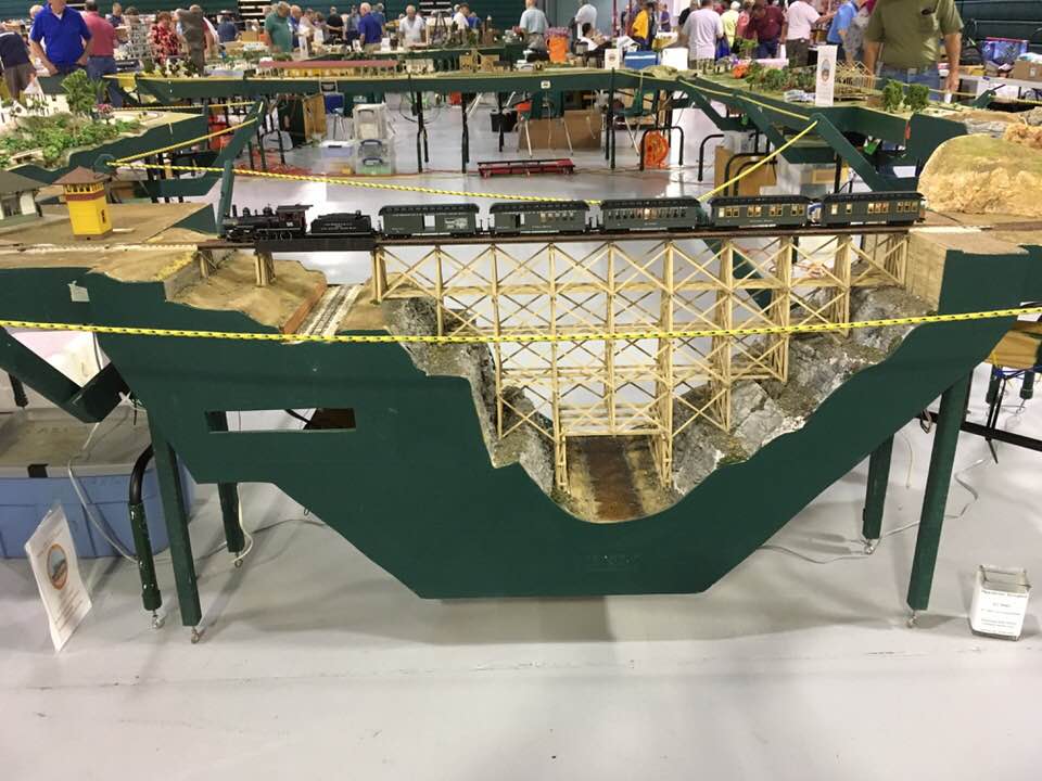
A passenger train crosses the impressive Henk Trestle.
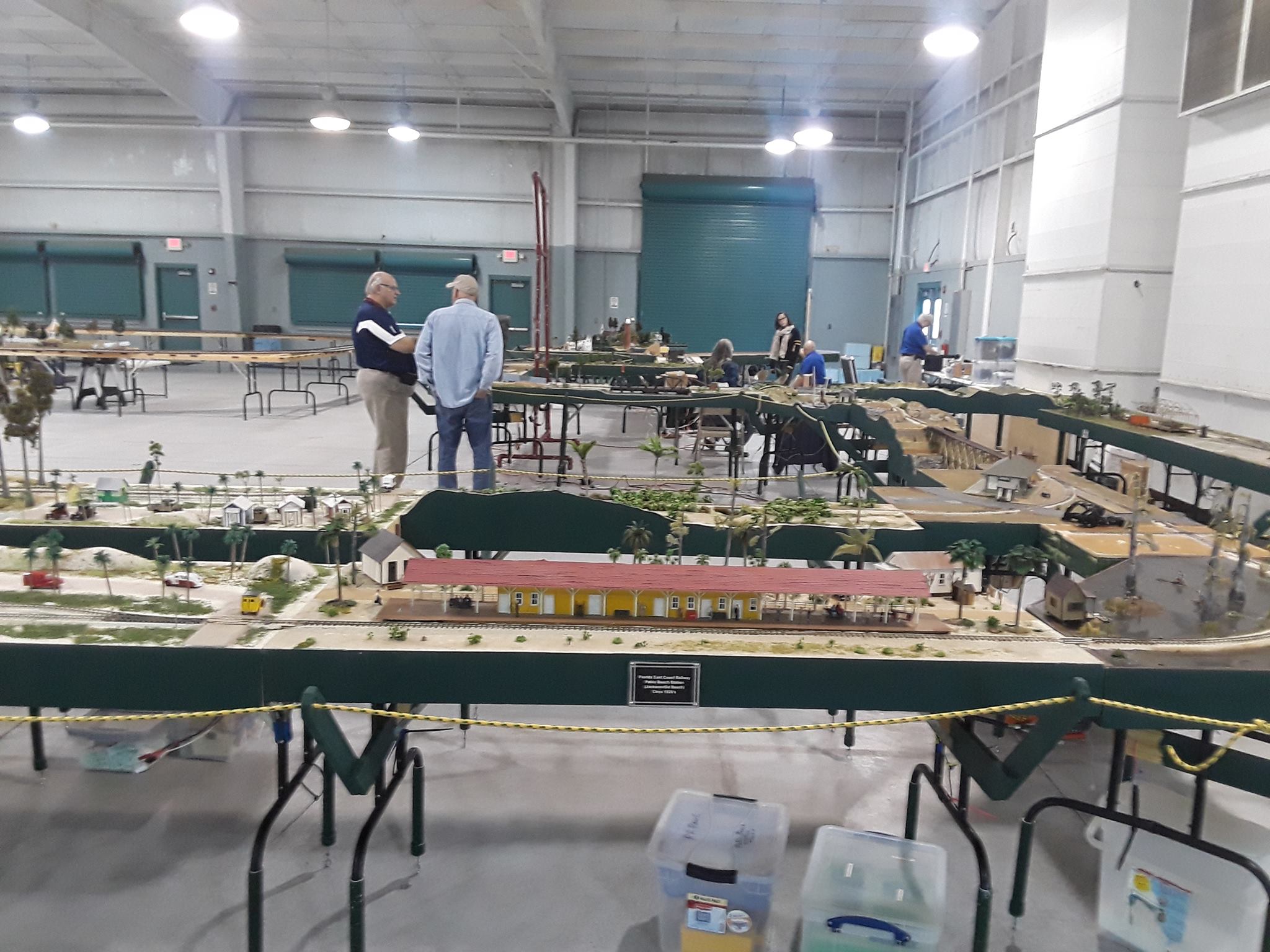
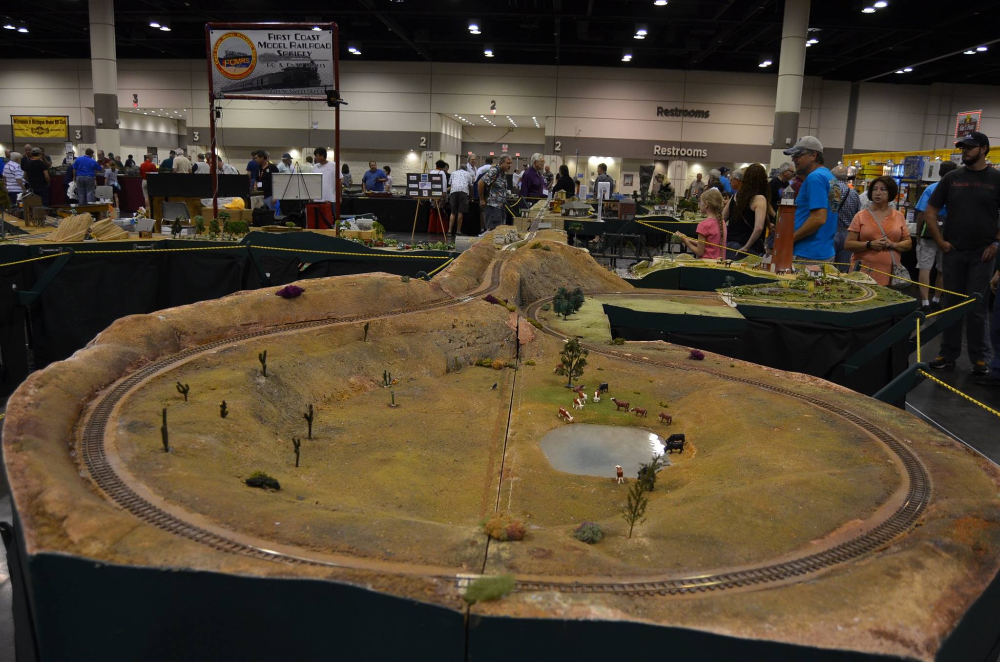
Overview shot of one setup.
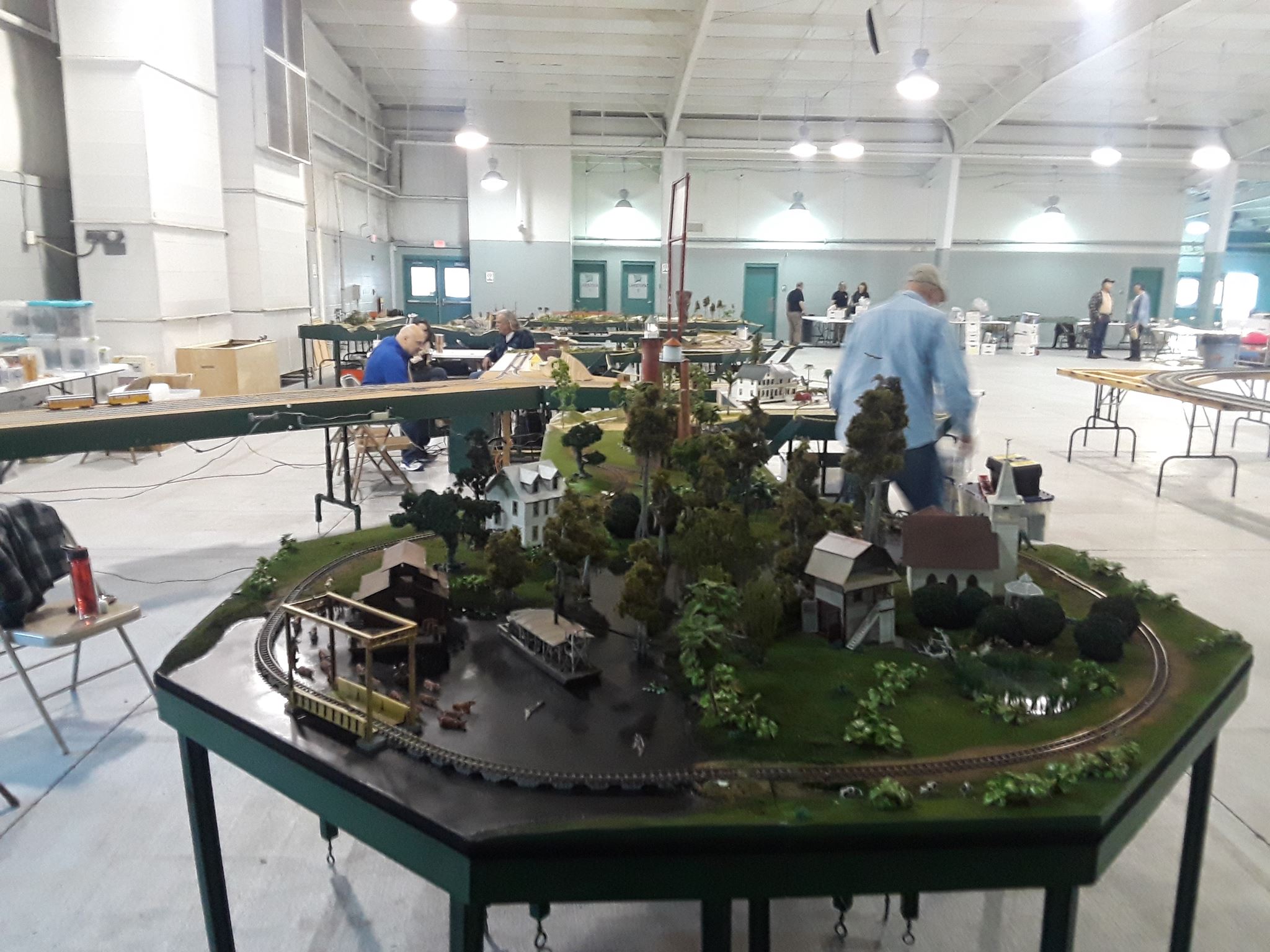
Same layout from the other end.
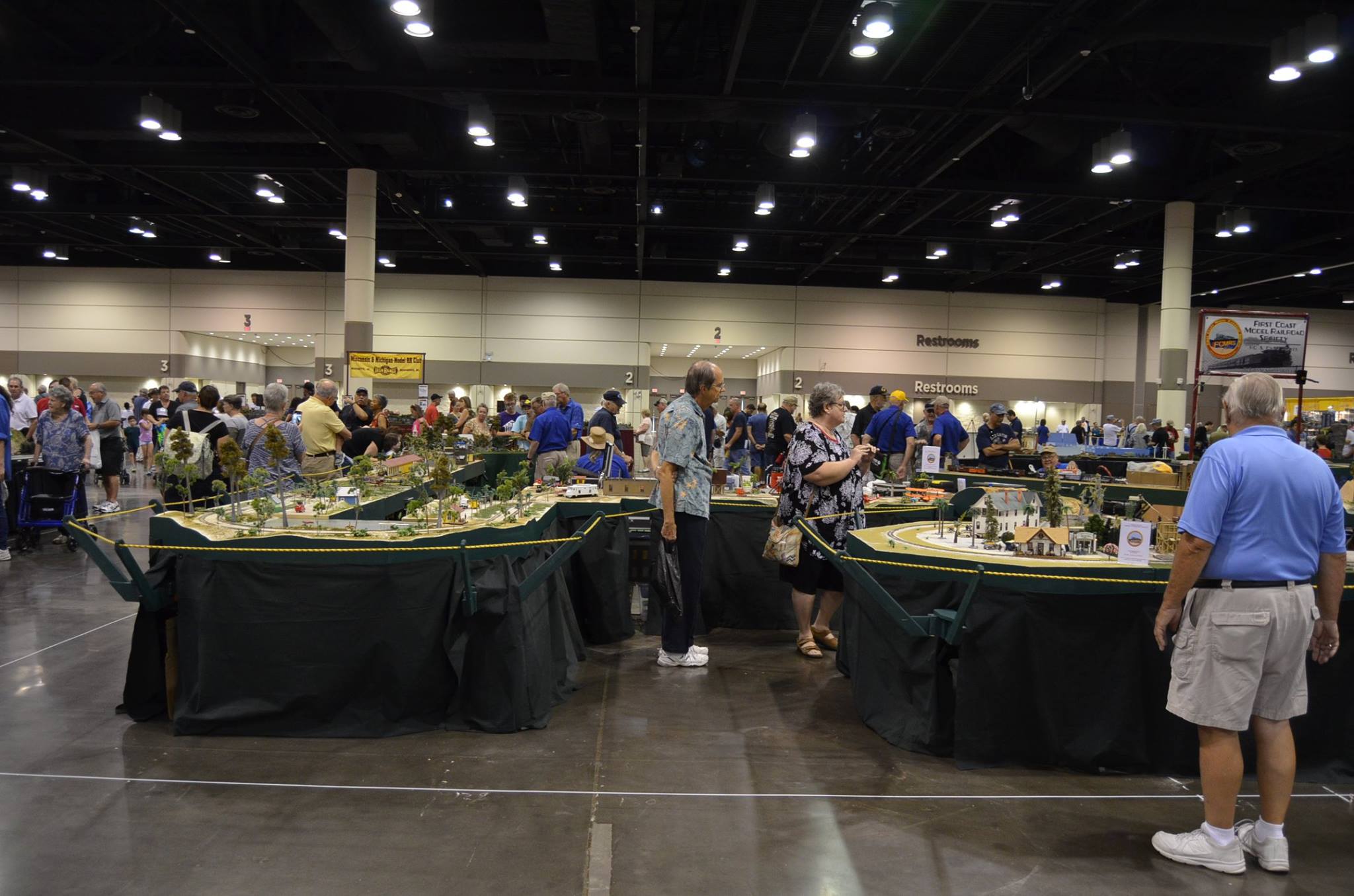
Part of the layout for the 2017 National Train Show.
Tanglefoot Curve at the NTS 2017 layout.
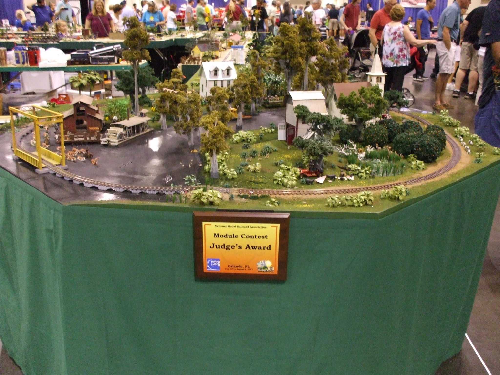
The award winning module by Dave and Debbie Renfrew.
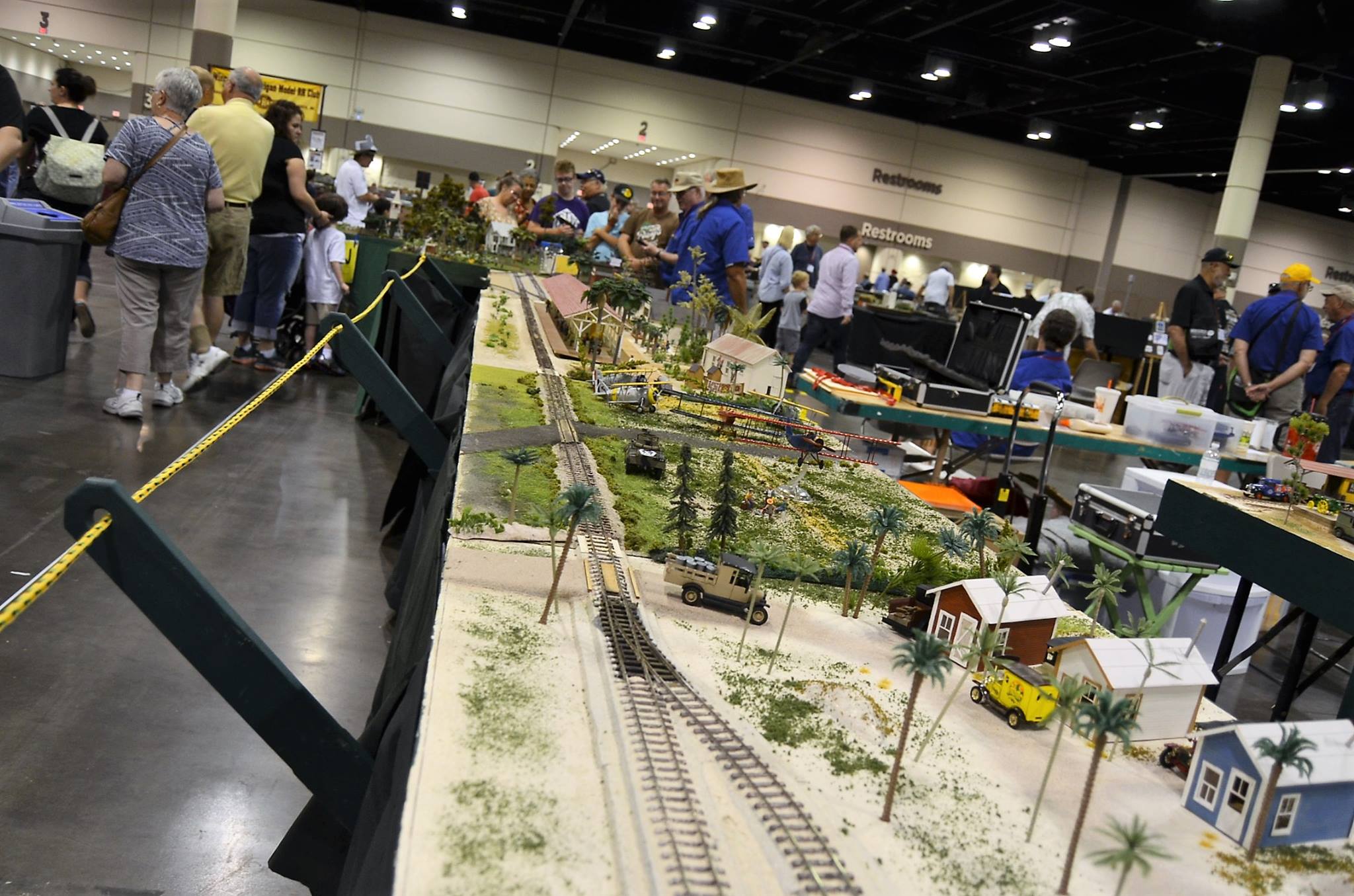
More of the NTS 2017 layout.
NTS 2017 layout track plan.
You Tube Videos
Several members have put up videos on You Tube:
- Galloping Goose
- Jacksonville and Atlantic Passenger Train
Module Construction Standards
Design Concept – The modules represent, mostly, a Florida theme because the scenery is relatively flat for transporting and is unique to the area where we live. We somehow ended up with a couple of “Colorado” type modules including a 6’ trestle module. Don’t ask me how. The club owns a few of the modules, or borrows them for the long term.
Set Up – Modules are designed to be located in any part of the layout from either side. With a couple of exceptions, all modules can be located in any part of the layout to meet operating needs and to make it interesting. We have not had the same layout design twice in the ten years we have been doing this.
General Size – You must be able to transport your module in your own vehicle. Also, you must be able to load it from home yourself, so keep it light. There is no more space up at the club to store additional modules.
This is especially true if the club runs out of trailer space. Otherwise, you may need to rent your own trailer. The club is currently renting two trailers and another private trailer to transport the modules. The club changes out modules for each show and is pretty much at optimum size layout for the shows. But we trade out modules all the time, so there is a good chance based on the design that your modules will be able to fit into a club trailer from time to time.
Most modules are built either 6’ long or 4’ long and are no less then 18” wide. All of these modules have legs. We also have 30”, 24”, 18” and a 12” long modules. These modules are called “floaters” because they do not have legs and are supported by the abutting modules. Modules are assembled together using spring clamps and C-clamps. There is an indexing pin used to align the modules and is centered on the main track of each module. Dan Marlowe is the keeper of the jig for drilling the indexing holes.
Heights – Currently, the modules have two heights we use, 36” to top of roadbed and 42” to top of roadbed. We can change the heights by changing the lengths of our PVC pipe leg extensions. The pipe leg extensions also have eyebolt screw adjusters to fine-tune the heights on uneven floors.
Construction – Generally, the modules are built on a ¼” plywood deck covered by one or two inches of building insulation foam. The end plates are ¾” thick 1 x 6 poplar. The owner determines the width. The edges of the plywood are framed with 1x2’s for attaching the sides and end plates. The sides are also ¼” plywood. The most success with the plywood has been the Sandi ply from Home Depot. It is affordable, has knot-free surfaces and is lightweight. The roadbed is also cut out of the plywood and glued on top of the foam. This makes for a rigid structure for the track. Legs are made from folding Banquet table legs from Home Depot. If your module is less than 28” wide, you’ll probably need to make a set of PVC legs to fit over the folding arms to be able to fold the legs up under the module. The folding legs are used to support the cantilevered-stanchions for the rope line, so anything different is doable but discouraged.
Track – Track currently used is On30 Code 100 Peco flex track. We tried Code 83 and it was not robust enough for module use. Micro Engineering has a new On30 code 100 that is supposed to be stronger than their earlier track. We have not tried it.
Minimum mainline radius is 30” with sidings at 27”, or 24”. There should be a 6” straight transition space at the end of each module. We use Atlas 3” snap track connectors (modified) to connect modules.
Mainline centerline set back from module front edge is 6”.
Turnouts should be PECO HO Medium or higher. The Peco On30 turnouts are used but not desirable. The Medium turnout has a 30” radius so that is why it is selected.
Electrical – A Digitraxx control system is used. Either by straight plug-in, radio control, or Wi-Fi control. The club only has a couple of handhelds. Members are encouraged to acquire their own handheld or use their cell phone (Wi-Fi). You’ll need to download the JMRI free App though.
We use Digitraxx AR-1 reversing units to reverses polarity at the reversing sections of the layout.
We use #14 stranded wire for the power buses. Red, black, white, green. White and green are not required now since each individual module is now required to provided lighting and animation power.
Anderson power poles are used to connect module to module. As a rule of thumb, the wiring harness should be the length of the module plus 2 feet (one foot for each end). Power drops are normal to HO or similar solid or stranded.
Finishing – The sides are painted with Glidden “Footpath” green in a Satin sheen from Home Depot. The surface area is first painted with a light colored latex paint to protect the foam from melting from other chemical paints, and then painted in a sand color – normally a Krylon stone-textured spray paint of white or tan. Ballast is made from Aquarium sand to represent Florida Limestone.
A document showing details of module construction can be found here.